Tag: ham_radio

Amateur Radio Starter Kit

radio : by Tommy — September 26th 2016, 07:16PM
radioI recently posted on Facebook for some friends about an incredibly cheap radio out of China. It's the Baofeng UV-5R.
The little dual-band radio has been the source of much consternation among the old guard of amateur radio because of it's cheap construction, low quality display, and some technical problems with the radio (some which make it technically illegal to operate on some frequencies). However, it is 100% legal to operate on the 2m amateur band (144-148MHz). The price of this radio is what makes all shortcomings able to be overlooked. It costs $25 on Amazon with free shipping for Prime customers!

Now, the radio is not a super great radio, but it's a phenomenal starter radio. (Or, as I call the one I keep in my car, a "burner" radio. I can drop it, lose it, or have it stolen and I simply would not care.) If one were to purchase this little capable radio for the mere $25 price tag, one should also get a couple of pieces of kit that should be standard: a better after-market antenna (Option 1 or Option 2) and a USB programming cable in order to program all the frequencies of nearby repeaters using software like CHiRP. All in, the whole kit still comes in around $40 which is still a fraction of the cost of a dual band radio from one of the major amateur radio manufacturers like Icom, Kenwood, or Yaesu.

Study, study
Anyone interested in amateur radio should consider studying for their license before dropping any money on a radio. While the radio is cheap, it's still money wasted if you can't use it because you don't have a license. The student guide's I most often recommend are the Technician study guide by Gordon West, WB6NOA, or the Technician study guide by the ARRL. Once you've studied a little, I recommend taking free online practice tests like HamStudy.org until you're consistently getting 75% or better. There are plenty of other online resources to help you study such as the YouTube series by Dave Casler and Ham College by the AmateurLogic guys.

Testing
Once you've studied, it's time to test. The Technician license is fairly easy enough. It's 35 questions, multiple choice, and the questions and answers are all public knowledge! There's no secret. Your test will be made up of the same questions with the same answer choices that you studied in the book or online. You only need to get 26 of them correct to get a passing score of 75%. Testing can usually be found within a short drive of wherever you live. The ARRL VEC has a huge number of testing locations put on by various local clubs, the W5YI Group also has a large group of test proctoring locations, and then the smallest of the three options is the Laurel VEC. (The cool thing with Laurel is that while there are so few clubs, they offer testing for free and are generally faster than the others in terms of processing your test results and getting you your license - so perhaps worth the drive to find a location!)

So hopefully that helps get you off and running with the cool amateur radio hobby I've enjoyed for quite some time now. I look forward to talking to you on the radio someday!

DUX Homebrew Arrow Yagi

radio : by Tommy — August 7th 2010, 11:36PM
radioDUX Homebrew Arrow YagiThis summer I attended the TI-2 Space workshop put on by the ARRL and DARA in Dayton, OH. We spent 4 days learning how to make contacts with orbiting satellites like AO-27, AO-51 and the International Space Station, just to name a few. The antenna we used was the dual-band Arrow II Antenna. I've owned one for years and really like it. I wish more people had them, but I think most people think spending $140 for an antenna that can only handle 10W is a bit much.

My aim was to make a cheap alternative to the Arrow that is easy to break down for transport and storage. I really like the idea of using aluminum arrow shafts for elements; they are lightweight, straight, weather resistant, and fairly inexpensive. Another nice feature is the #8-32 threaded insert for broad heads that almost every arrow comes with.

I spent a couple of hours reviewing all the "cheap" and "ugly" yagi designs, as well as others like the "tape measure" and even a new-to-me "backpacker" design. They each have their own advantages and loyal followers.

I finally based my antenna design on one found in the ARRL Handbook from 1999. While not an exact replica, my design is very similar. I had decided to go with the through-boom design like the Arrow, as opposed to side-mounted because it is, in my opinion, cheaper. After buying 6 arrows and a quick trip to Lowe's I had a length of #8-32 all-thread and a piece of 3/4" conduit to use as the boom. I marked a straight line down the center of the boom to give me a point of reference, measured out the spacing holes, made sure I was drilling square and level and got to work. After the 3 holes were drilled, I cut 2.5" lengths of all thread for the director and reflector. Since I was going with the split driven element design of the IDX yagi, I would not need threading for the Driven Element, I'd use machine screws for that. Originally I planned to use nylon 8-32 all-thread to go through the boom for the driven element, and feed each side independently similar to the Tape Measure Yagi, but I couldn't find nylon all-thread, and the longest nylon screws to be found came up an inch too short.

I cut a length of RG-58 cable and soldered on two o-ring connectors to slip over the machine screws before screwing on an arrow.
Lastly I cut each arrow to the appropriate length, which worked out to:
- 19 5/8" for each Reflector arrow
- 18 1/8" for each Driven arrow
- 17 1/8" for each Director arrow
The measurements came from IDX's lengths, subtracting 3/4" (for the boom) and then divided by 2 to give me the necessary length for each arrow.
I used a cutoff wheel and my air compressor to cut the arrows to length instead of a hacksaw. The cutoff wheel leaves a clean cut as opposed to sawing.

After putting my MFJ-269 analyzer on the yagi, I found the lowest SWR to be about 1.4 right around the target frequency of 144.490 MHz. Not too shabby for a first yagi.
For those taking my lead, I found it helpful to feed the yagi as perpendicular to the boom as possible. It is also somewhat important for the O-ring feedline connectors to be on the same side of the boom as the arrow.

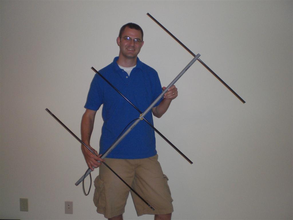
Here's a pic of me holding the 2m yagi. It's a bit larger than the commercially made Arrow.

update: I've been asked by more than one person why the split driven element. As you read above, it was semi forced on me by necessity. I needed it to be split for mechanical reasons. the screws going through the boom serve as a match, negating the need for the "hairpin" match from the tape measure yagi or a gamma match. The driven elements being split probably do affect the radiation pattern in the long-field, but perhaps only skew the pattern more in one direction.
(TLDR: it's easier that way and it just works!)

update #2: Hello Hack-A-Day! Yes, you can talk to the space station and many other amateur radio satellites.
update #3: Okay, for those that are interested, I'll be putting together kits if you want. Price to be determined based on what you want/need. You can email me at tommy@neodux.com for more info.

Elecraft KXAT1 Antenna Tuner

radio : by Tommy — April 19th 2009, 06:50PM
radioI recently added the KXAT1 antenna tuner kit to my Elecraft KX1. The antenna tuner allows me to automatically tune up any non-resonant antenna quickly. Construction took one evening. As usual, winding the toroids was perhaps the most tedious part, but "zen-like" while I was doing them (as I heard it put by someone). I did have trouble with the transformer. It can be tricky and I'll warn other kit builders to check out this thread if they have trouble. I also found some pictures from a japanese ham helpful, but I've since lost them. :(

After building and installing the tuner, I purchased 40ft of some "silky" 26AWG wire from TheWireMan as suggested by Elecraft. I cut the wire to give me two lengths. One length is 24ft and the other 16ft. The 24ft length is my radiating element and the 16ft acts as my ground. The tuner quickly finds a nice 1.1-1.0 match and gives me full KX1 power out (~4W). It makes for a very lightweight, field-portable antenna. I can also use my crappie poles to elevate one end if trees are unavailable.

I use a BNC-to-binding post that I purchased at EPO in Houston. While at EPO, I also picked up a small 12V 1.3Ah gel cell battery. The UB-1213 is about 3.8" x 1.7" x 2" and provides adequate power for portable QRP work. If I was going to operate for very long, I may go with a little larger capacity gel cell, but for now this makes a very lightweight and super portable setup that allows me to get one the air quickly.

Elecraft KX1

radio : by Tommy — April 5th 2009, 06:27PM
radioAbout two weeks ago I completed construction of my Elecraft KX1 ham radio kit (serial #2182). It wasn't the easiest build I've done, but definitely the most fun. The purchase was funded almost totally by referral bonuses from Dreamhost. When anyone signs up for an account with my referral link I get a kick-back. I had let the bonuses build up over time and eventually had enough to cover the radio, but I digress.

The KX1 is a "trail-friendly", portable CW ham transceiver. There's plenty of other sites that will give you more detailed information about this gem of a radio. I finally got to use mine yesterday for more than a couple of minutes and I must say I totally love it. The receiver is great, the noise floor is low, the filters are tight, and the features are really packed into this tiny radio.

My antenna was a random wire made from speaker wire with one end elevated to 20' using a BnM Black Widow 20' Crappie Pole purchased at Bass Pro Shop in Shreveport, LA. The antenna sloped down to my BLTPlus antenna tuner which tuned the random wire without any problem. I had the tuner hooked into the KX1 with a short piece of BNC cable.

In short order I was copying stations on 7.030Mhz (40m QRP) and trying to copy the faster stations lower down on the band. I had to tighten up the filters because of the sheer number of signals I was able to pull in. I wasn't able to raise any station due to my diminished transmit power. (I was running off of internal AA batteries because my gel cell hadn't been charged in quite some time.) I was also impatient due to the strong wind, fading daylight and biting insects. I'm going to try again later this week and see if I can't finally capture that elusive QRP contact with this fun little radio.

update: I now have the KXAT1 auto tuner installed.

Rockmite 20m

radio : by Tommy — December 22nd 2008, 12:57AM
radioRockmite 20mAfter almost a year of procrastination I got around to finishing a Rockmite 20 radio kit. The Rockmite is a single-frequency crystal-controlled ("rock-bound") low-power CW HF radio. Say that 10 times fast!

I bought the kit sometime last year and just never finished building it. I had all of the components soldered in, but I never mounted the board in any enclosure. W5USJ, Chuck, Don, K5DW, gave me a metal enclosure during a North East Texas QRP Club meeting. It wasn't until last Friday that did anything with it. I knew the Rockmite needed a home, and here was a nice case for it. I drilled some holes in the cabinet, more or less eyeballing it. They're not perfectly aligned, but pretty close. So now the little radio is mounted, all of the connectors are soldered in and the radio is functional.

It only puts out about ½W at 14.060MHz, on the 20m amateur radio band, but because I mostly operate during the afternoons, 20m is my favorite band for now. I may need to boost myself up to a "full gallon" QRP and get a 5W amplifier like the one Chuck designed, which I might get from QRPme.

Also on my "to do" list, is to add a PicoKeyer chip to the radio which greatly adds to the experience of using it.

update: I got the PicoKeyer chip installed this afternoon. I love the features it provides. The Memory Keyer is vital for QRP work and the hands-free "Tune" feature is great for field-portable antennas. Most of the other features I don't use, but I still think the chip should be incorporated into the original design.